Topology guide at a glance
- Primary task
- Choose and build a logical network topology
- Best beginner design
- Star topology with one central switch
- Topology types
- Bus, star, ring, mesh, tree, and hybrid
- Verification
- Link state, IPv4 plan, ping, and Simulation mode
- Current release check
- Packet Tracer 9.0.0; no newer verifiable public release found
- Official source
- Cisco Networking Academy Resource Hub
Choose topology from requirements, not appearance
Start with failure, scale, cost, and traffic requirements. Count endpoints, identify critical services, and decide whether one broken cable should isolate one device or a whole segment. A Packet Tracer diagram should explain a requirement rather than decorate the workspace.
Separate physical topology from logical behavior. Label devices, interfaces, subnets, VLANs, and expected paths so another learner can understand the design before opening configuration windows.
Compare six network topology types
Bus shares one backbone; star connects endpoints to a central switch; ring links each node to neighbors; mesh adds alternate paths; tree expands stars in layers; hybrid combines patterns for a larger design.
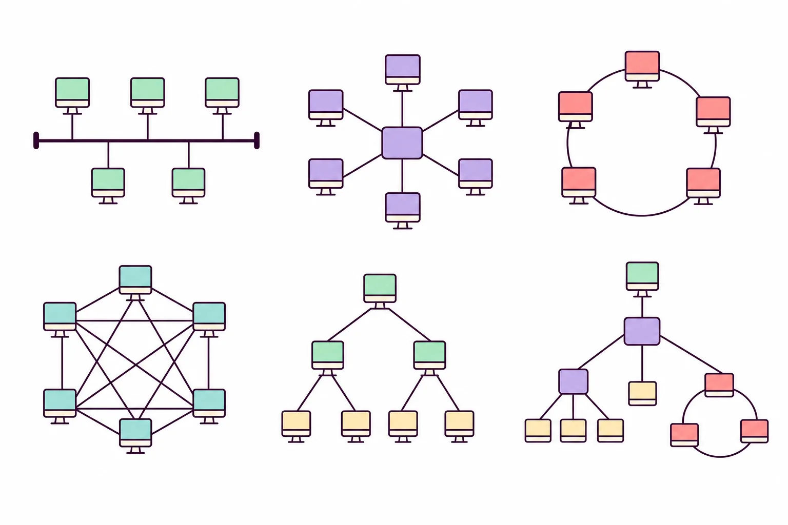
| Type | Best use | Main tradeoff |
|---|---|---|
| Bus | Legacy shared-medium concepts | One backbone affects the segment |
| Star | Beginner Ethernet LANs | Central switch is critical |
| Ring | Ordered neighbor flow | Simple rings have limited resilience |
| Mesh | Redundant routed designs | More links and configuration |
| Tree | Hierarchical campus design | Upper layers affect branches |
| Hybrid | Real mixed environments | Needs clear documentation |
Build a star topology in Packet Tracer
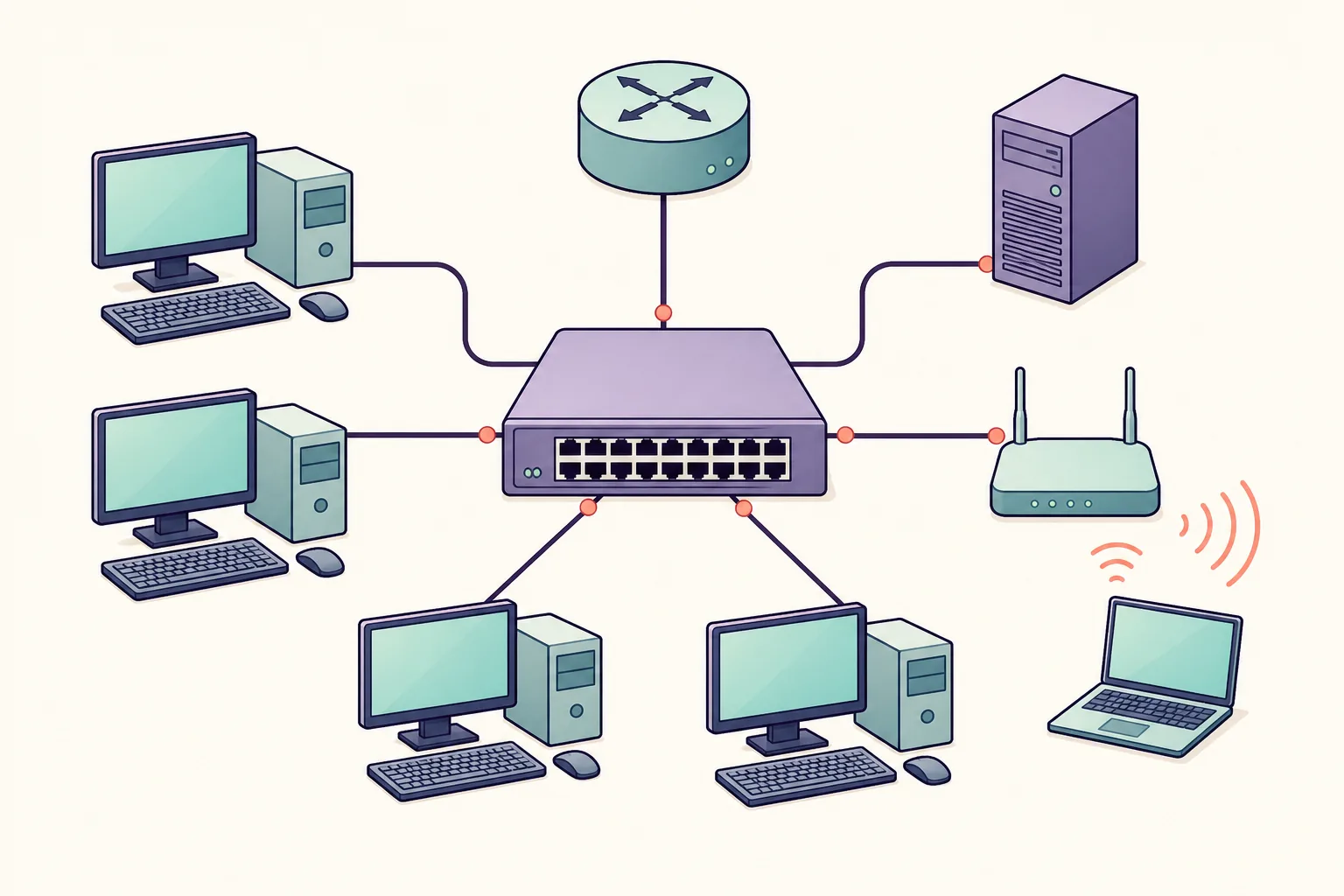
Place one switch in the center, add four PCs, and connect each PC to a different access port with copper straight-through cabling. Wait for active links, rename devices, and save a clean baseline before assigning addresses.
A star makes faults easier to isolate: one access cable usually affects one endpoint, while a failed central switch affects the whole LAN.
- 1
Place and name devices
Use one switch and four PCs.
- 2
Cable separate ports
Use copper straight-through links.
- 3
Assign one subnet
Record unique IPv4 addresses.
- 4
Test and observe
Ping, then inspect ARP and ICMP.
Add an addressing plan and labels
Use 192.168.10.11 through 192.168.10.14 with mask 255.255.255.0. A default gateway is unnecessary until a router connects this LAN to another network. Record every address before typing it.
For larger topologies, use one subnet per VLAN or routed link. Consistent labels such as PC-A, SW1, R1, G0/0, VLAN 10, and 192.168.10.0/24 make troubleshooting faster.
Test topology in Realtime and Simulation modes
Check port lights, run ipconfig, and ping a nearby device in Realtime mode. Then filter ARP and ICMP in Simulation mode, send a Simple PDU, and step through address resolution, echo request, and reply.
Troubleshoot one layer at a time
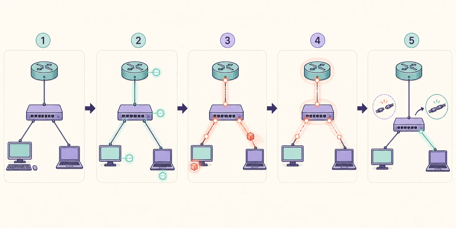
If ping fails, inspect power and cable type, interface state, address and mask, VLAN membership, default gateway, route table, and ACL. Change one item, test again, and keep the output that proves the result.
Do not solve a logical error by randomly adding links. Confirm the intended path on the diagram, then compare it with interface state, show commands, and Simulation events.
Packet Tracer topology FAQ
Which topology is best for a Packet Tracer beginner?
Start with a star topology using one switch and two to four PCs.
Is a Packet Tracer diagram physical or logical?
It can show both: placement and cables are physical; VLANs, subnets, routes, and packet paths are logical.
How do I test a network topology in Packet Tracer?
Check links and addresses, ping endpoints, then inspect ARP and ICMP in Simulation mode.
Why is my topology not connecting?
Check cable, port, IP address, mask, VLAN, gateway, routes, and ACLs in that order.
Official references
- Cisco Packet Tracer 9.0 announcement
Cisco Community release announcement.
- Cisco Packet Tracer download resources
Official Cisco Networking Academy resource hub.