
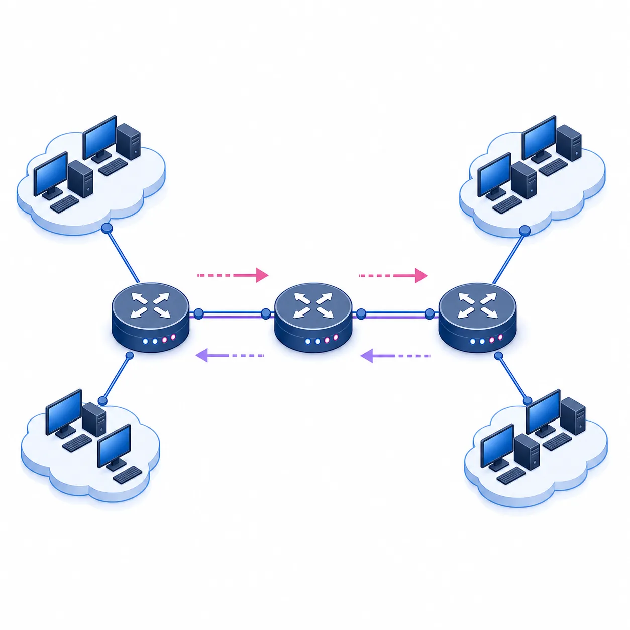
Static routing lab at a glance
- Primary task
- Configure and verify IPv4 static routes between three routers
- Example topology
- R1 — R2 — R3 with one LAN behind each edge router
- Core command
ip route <network> <mask> <next-hop>- Proof commands
show ip route,ping, andtraceroute- Safety rule
- Keep a clean PKT copy and record the expected path before changing syntax
Plan a three-router static routing topology
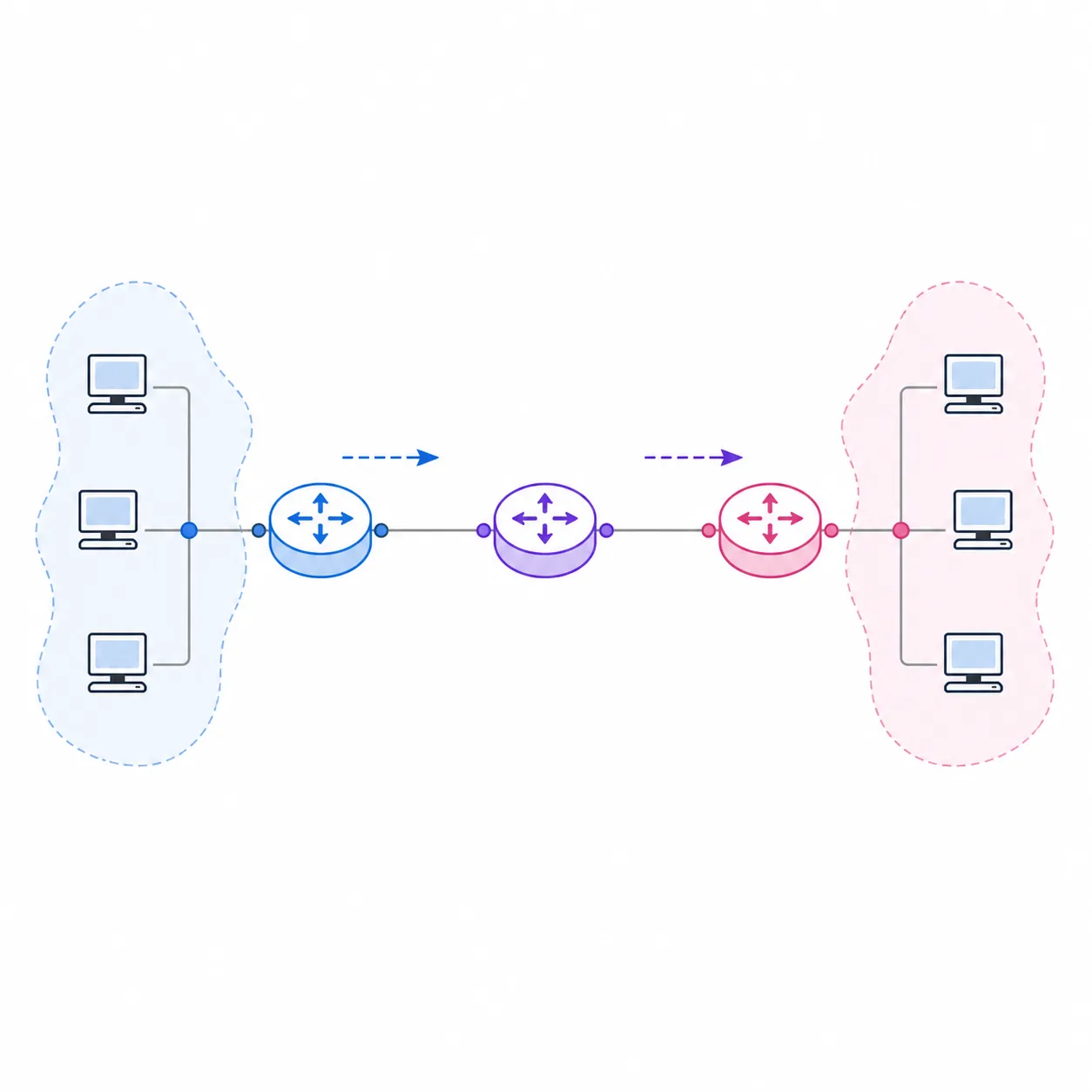
Use R1 and R3 as the edge routers and R2 as the transit router. Put one small LAN behind each edge router so the end-to-end test has a clear source and destination. In this example, R1 serves 192.168.10.0/24, R1-to-R2 uses 10.0.12.0/30, R2-to-R3 uses 10.0.23.0/30, and R3 serves 192.168.30.0/24. The exact interface names can change with the router model; the network relationships must not.
Before opening the CLI, write down the route that each router needs. R1 needs a path to the R3 LAN through R2. R3 needs a return path to the R1 LAN through R2. R2 needs one route to each edge LAN. This is the part that prevents the common one-way-ping mistake: a forward route without a return route is not a complete design.
Connect the routers, wait for the links to come up, and save a clean PKT file. A static route is only useful when its next hop is reachable through a working interface. If the physical link, IP address, or subnet mask is wrong, adding more route commands will hide the original problem instead of fixing it.
- 1
Place and name the devices
Add three routers and at least one PC on each edge LAN. Use names such as R1, R2, R3, PC-A, and PC-C so the notes match the topology.
- 2
Create the address plan
Record every interface address, mask, LAN network, and intended next hop before entering configuration mode.
- 3
Save a baseline
Save a clean PKT copy after cabling and basic addressing, before static routes are added.
- 4
Define the proof
Expect local gateway pings first, then an R1-to-R3 host ping and a traceroute that crosses R2.
| Segment | Device/interface | Address | Purpose |
|---|---|---|---|
| R1 LAN | R1 G0/0; PC-A | 192.168.10.1/24; 192.168.10.10/24 | Source network |
| R1-R2 | R1 G0/1; R2 G0/0 | 10.0.12.1/30; 10.0.12.2/30 | Transit link one |
| R2-R3 | R2 G0/1; R3 G0/1 | 10.0.23.2/30; 10.0.23.3/30 | Transit link two |
| R3 LAN | R3 G0/0; PC-C | 192.168.30.1/24; 192.168.30.10/24 | Destination network |
Configure interfaces and prove the connected networks first
Start with interface configuration, not static routes. On each router, enter the interface connected to a LAN or transit link, assign the address and mask, and use no shutdown. On the PCs, set an address in the correct LAN, use 255.255.255.0 for this example, and set the edge router address as the default gateway. If a router model uses FastEthernet instead of GigabitEthernet, adapt the interface name while preserving the address plan.
Test each directly connected hop before routing across the whole topology. From PC-A, ping 192.168.10.1. From R1, ping 10.0.12.2. From R2, ping 10.0.23.3. From PC-C, ping 192.168.30.1. These tests establish that the next hop named in a future static route is actually reachable.
Use show ip interface brief and show ip route connected on every router. An interface should be up/up, and the connected network should appear in the routing table. Do not continue to static-route configuration when the transit link is administratively down or the connected route is missing.
- 1
Address R1
Configure the R1 LAN interface as 192.168.10.1/24 and the R1-R2 link as 10.0.12.1/30, then enable both interfaces.
- 2
Address R2
Configure the transit interfaces as 10.0.12.2/30 and 10.0.23.2/30, then verify that both neighbors answer.
- 3
Address R3
Configure the R3-R2 link as 10.0.23.3/30 and the R3 LAN interface as 192.168.30.1/24.
- 4
Check connected routes
Run
show ip interface briefandshow ip routebefore adding any remote-network route.
If a connected neighbor does not answer, fix cabling, interface state, address, or mask first. A static route cannot compensate for a broken next hop.
Add static routes with the correct destination and next hop
The basic IPv4 syntax is ip route destination-network subnet-mask next-hop. Read it from left to right: which remote network should be reached, what mask identifies that network, and which reachable router should receive the packet next. The destination is not the remote host address, and the next hop is not the final destination host.
For this topology, R1 sends traffic for 192.168.30.0/24 to 10.0.12.2. R2 sends traffic for 192.168.10.0/24 to 10.0.12.1 and traffic for 192.168.30.0/24 to 10.0.23.3. R3 sends traffic for 192.168.10.0/24 to 10.0.23.2. The four entries create both directions across the lab.
After entering each command, read it back with show running-config and check the routing table. The route should become usable only when the next hop can be resolved through a connected interface. If you prefer an exit interface, use it only when the topology and platform behavior make that choice unambiguous; a reachable next hop is easier for a beginner to reason about in a multi-access segment.
- 1
Add the R1 remote-LAN route
On R1, use
ip route 192.168.30.0 255.255.255.0 10.0.12.2. - 2
Add both R2 edge-LAN routes
On R2, point 192.168.10.0/24 to 10.0.12.1 and 192.168.30.0/24 to 10.0.23.3.
- 3
Add the R3 return route
On R3, use
ip route 192.168.10.0 255.255.255.0 10.0.23.2. - 4
Save after verification
Use
copy running-config startup-configonly after the route table and end-to-end tests are correct.
| Router | Destination network | Next hop | Expected route meaning |
|---|---|---|---|
| R1 | 192.168.30.0/24 | 10.0.12.2 | Send the remote LAN toward R2 |
| R2 | 192.168.10.0/24 | 10.0.12.1 | Return traffic toward R1 |
| R2 | 192.168.30.0/24 | 10.0.23.3 | Forward traffic toward R3 |
| R3 | 192.168.10.0/24 | 10.0.23.2 | Return traffic toward R2 |
Verify the route table, ping path, and Simulation mode
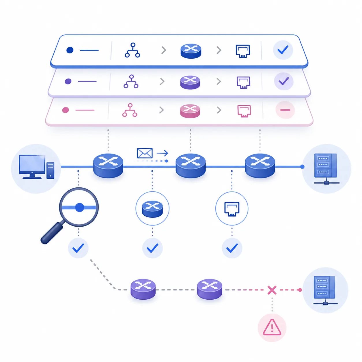
Verification should move from the router to the host and then across the full path. On each router, run show ip route and look for an S entry for every remote LAN. Confirm that the code points to the intended next hop and that there is no typo in the destination mask. A route table is evidence of the forwarding decision; it is more useful than a single successful ping with no explanation.
Next, test in layers: ping each local gateway, ping the directly connected neighbor, ping the remote gateway, and finally ping the remote host. From PC-A, a successful ping to 192.168.30.10 proves that R1, R2, R3, both LAN gateways, and the return path are all working. Use traceroute where the Packet Tracer host tools expose it to see the hop sequence.
Simulation mode is useful after the basic route table is correct. Filter for ICMP, send a Simple PDU or ping, and step through the packet. If the packet stops at a router, inspect the router's route table and the next hop. If the request reaches the destination but the reply does not return, look for the missing reverse route rather than changing the source host.
- Run
show ip interface briefto prove the relevant interfaces are up/up. - Run
show ip routeand confirm every remote LAN has an S route with the expected next hop. - Use
show running-configto compare the saved command with the written address plan. - Ping the local gateway, each transit neighbor, the remote gateway, and the remote host in that order.
- Use Simulation mode or traceroute to identify the first hop where the packet stops.
| Check | Expected evidence | If it fails |
|---|---|---|
| Interface state | up/up on the required link | Check cable, interface name, address, and no shutdown |
| Connected route | The local subnet appears as connected | Fix the interface mask or state before adding routes |
| Static route | An S entry points to a reachable next hop | Compare destination, mask, and next-hop address |
| End-to-end ping | Request and reply cross R2 | Check the return route and both host gateways |
Troubleshoot static routes without changing everything at once
The most common failure is a missing return route. A request can travel from R1 to R3 while the reply has no route back to 192.168.10.0/24. The second common failure is a wrong mask: 192.168.30.0/24 and 192.168.30.0/25 are different destinations, so the route may not match the packet you intended to forward.
Check the first failing layer and change one variable at a time. If the local gateway fails, the issue is not a remote static route. If the neighbor ping fails, fix the transit link. If both neighbors work but the remote LAN fails, compare the S entries on the edge routers and the transit router. If a request arrives but no reply returns, inspect the reverse path and the PC default gateway.
Do not place course assessment answers or copied PKT files on a troubleshooting page. Build a small reproducible topology, record the command output, and explain why the correction works. That produces a lab you can rebuild later instead of a one-time paste.
- Keep a written source-to-destination path beside the CLI; it is the fastest way to catch a reversed next hop.
- Use a clean PKT copy when testing a second approach so old routes do not obscure the result.
- Remove or correct a wrong entry deliberately; do not add several competing routes to make the table look busy.
- If the lab is growing or routes change often, compare this static design with a separate OSPF guide rather than mixing protocols casually.
| Symptom | Check first | Likely cause | Useful evidence |
|---|---|---|---|
| Local gateway fails | Host address and edge interface | Wrong mask, cable, or shutdown interface | PC IP panel and show ip interface brief |
| R1 cannot ping R2 | Transit addresses and link state | Wrong /30 pair or interface state | Neighbor ping and connected route |
| One-way remote ping | Route on the destination side | Missing return route or host gateway | show ip route on R3 and PC settings |
| S route is missing | Command syntax and mask | Typo or wrong destination network | show running-config and route table |
| Route exists but packet stops | Next-hop reachability | Next hop is not connected or path is down | Simulation mode and neighbor pings |
Know when static routing is the right Packet Tracer lesson
Static routes are useful when the topology is small, the path is predictable, and you want to see exactly how a router chooses a next hop. They are also a good first routing exercise because the route table changes are easy to explain. They become harder to maintain when you add many routers, multiple backup paths, or frequent topology changes.
A Layer 3 switch can route between VLANs with a different design, while OSPF can exchange routes dynamically. Those are related but separate learning goals. Finish the static-route verification here first, then move to the VLAN setup or a future dynamic-routing guide when the page intent changes.
This page teaches a reproducible lab method. Cisco controls the Packet Tracer package, platform support, and account requirements; confirm those details in the official Resource Hub.
Packet Tracer static routing FAQ
What is the basic static route command in Packet Tracer?
Use ip route destination-network subnet-mask next-hop, for example ip route 192.168.30.0 255.255.255.0 10.0.12.2. The destination is the remote network and the next hop must be reachable.
Why does the ping work in one direction only?
The forward router may know how to reach the destination while the destination router has no route back to the source network. Add and verify the reverse route, then check the host default gateway.
Should I use a next-hop address or an exit interface?
A reachable next-hop address is usually easier to understand in a beginner multi-router lab. An exit interface can be appropriate on point-to-point links, but use the syntax supported by the router model and verify the resulting route.
Which commands verify static routes?
Use show ip route for S entries, show running-config to read the configured command, ping for reachability, and traceroute or Simulation mode to inspect the path.
Do I need a default route for this three-router lab?
No. Explicit routes to the remote LANs make the learning objective clearer. A default route is useful when one router has a single upstream exit, but it must not hide a missing specific route during practice.
Can a Layer 3 switch replace router-on-a-stick for this exercise?
It can provide inter-VLAN routing with a different design, but it changes the lesson. Keep the static-route lab focused on routed links between routers, then study Layer 3 switching separately.
Is OSPF the same as static routing?
No. Static routing is entered manually on each router. OSPF exchanges routing information dynamically. Do not mix the two until you can explain which route should win and why.
When should I save the Packet Tracer file?
Save a clean baseline before routing, save a working copy after interface verification, and use copy running-config startup-config after the final route table and end-to-end tests pass.
Official references
- Cisco Networking Academy Packet Tracer
Official product and access context; Cisco controls current package and account requirements.
- Cisco Networking Academy Resource Hub
Official destination for current Packet Tracer resources; sign-in or course access may be required.
- Cisco static routing support area
Official Cisco support area for static-routing concepts and IOS guidance; command availability can vary by platform.