
VLAN lab at a glance
- Primary task
- Create VLANs, access ports, a trunk, and inter-VLAN routing
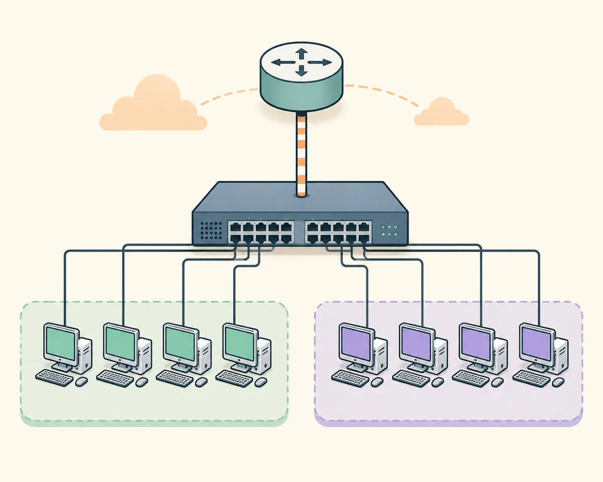
- Example topology
- One switch, one router, four PCs, and two IPv4 VLANs
- VLAN plan
- VLAN 10 = 192.168.10.0/24; VLAN 20 = 192.168.20.0/24
- Key checks
- show vlan brief; show interfaces trunk; show ip route
- Version check
- Cisco 9.0.1 signal checked August 7, 2026; confirm the package after sign-in
- Official source
- Cisco Networking Academy Resource Hub
Plan the Packet Tracer VLAN setup before typing commands
Start with one switch named SW1, one router named R1, and four PCs. Put PC-A and PC-B in VLAN 10, and PC-C and PC-D in VLAN 20. Connect SW1 to R1 with one link that will become an 802.1Q trunk. A small, explicit topology makes it easier to tell a VLAN mistake from a cable, address, or interface mistake.
Use the address plan 192.168.10.0/24 for VLAN 10 and 192.168.20.0/24 for VLAN 20. Give R1 the gateway addresses 192.168.10.1 and 192.168.20.1 on subinterfaces. For the hosts, use 192.168.10.11 and .12 in VLAN 10, 192.168.20.11 and .12 in VLAN 20, and set the matching gateway on every PC. Save a clean PKT copy before adding routing so you can return to a known baseline.
The goal is two separate Layer 2 broadcast domains with a deliberate Layer 3 path between them. Same-VLAN pings should work after access-port configuration. Cross-VLAN pings should fail until the trunk, router subinterfaces, and host gateways are all correct. That sequence gives every step a clear success test.
- 1
Place and name devices
Add SW1, R1, four PCs, and rename them so the topology and notes agree.
- 2
Write the address table
Record each PC address, mask, VLAN, and gateway before configuring the switch.
- 3
Build a baseline
Connect devices, check link state, and save a clean PKT file before segmentation.
- 4
Define the proof
Test same-VLAN reachability first, then test cross-VLAN reachability after routing.
Create VLANs and assign access ports
Open SW1's CLI and create the VLANs with descriptive names. The exact switch model can change interface names, but the configuration idea is stable: create VLAN 10 and VLAN 20, then place each end-device port in the intended access VLAN. An access port belongs to one VLAN; it does not carry a tagged list of VLANs like a trunk.
For a typical layout, place PC-A and PC-B on FastEthernet 0/1-0/2 and PC-C and PC-D on FastEthernet 0/3-0/4. Use show vlan brief after each group. The output should show the access ports under the correct VLAN. If the port is missing, check that you used the correct interface range and did not leave the port in the default VLAN.
Configure the hosts from Desktop > IP Configuration. A host in VLAN 10 needs a 192.168.10.x address and gateway 192.168.10.1; a host in VLAN 20 needs a 192.168.20.x address and gateway 192.168.20.1. At this stage, verify same-VLAN behavior and do not treat a failed cross-VLAN ping as a routing problem yet.
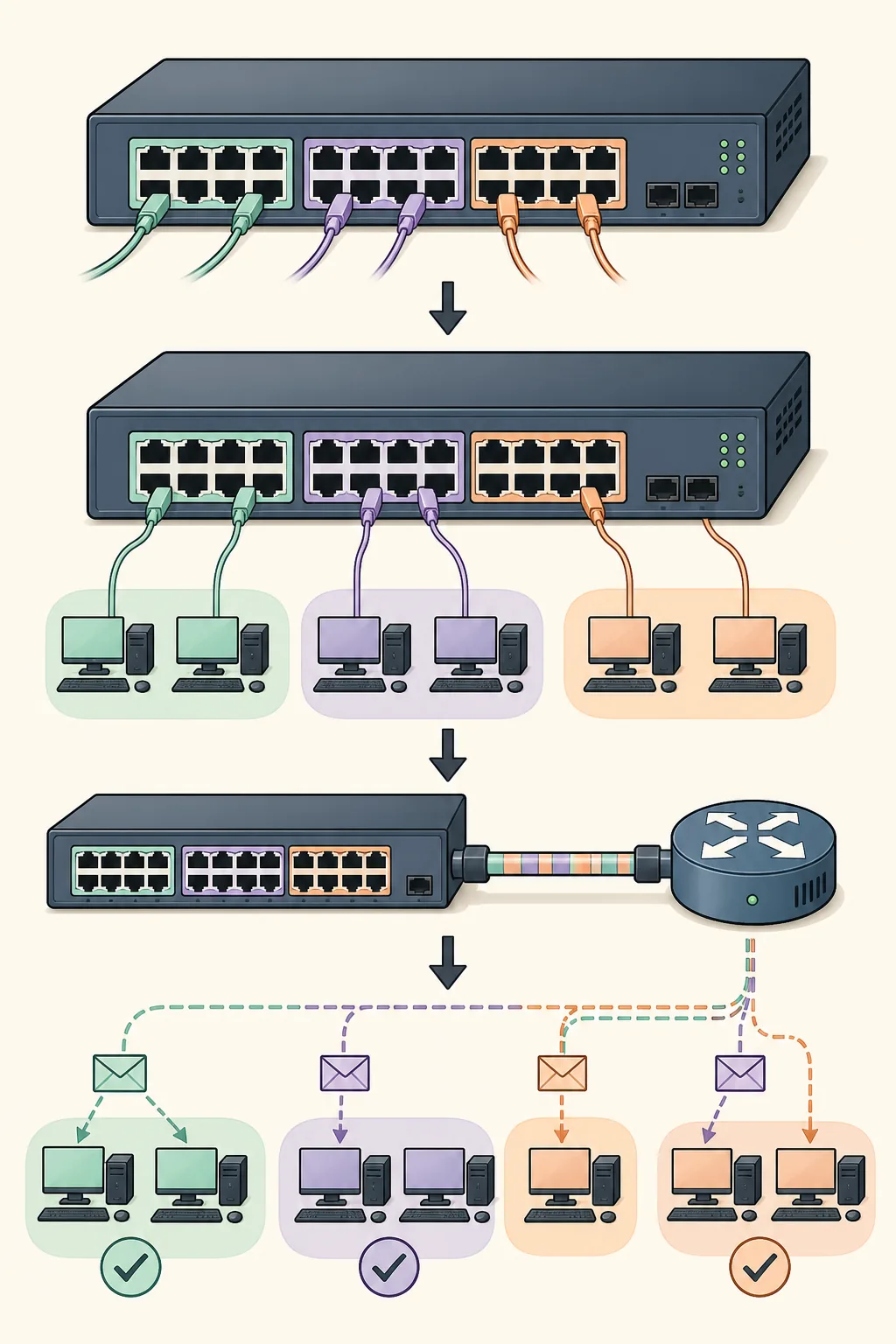
- 1
Create VLAN 10
Use
vlan 10and a name such as USERS_A, then exit VLAN configuration. - 2
Create VLAN 20
Use
vlan 20and a name such as USERS_B. - 3
Assign access ports
Enter each interface, set
switchport mode access, and apply the matchingswitchport access vlan. - 4
Verify membership
Run
show vlan briefand confirm every PC port appears under the intended VLAN.
| Device port | Role | VLAN | Expected host network |
|---|---|---|---|
| Fa0/1-0/2 | PC-A and PC-B access ports | 10 | 192.168.10.0/24 |
| Fa0/3-0/4 | PC-C and PC-D access ports | 20 | 192.168.20.0/24 |
| Gi0/1 | SW1-to-R1 uplink | Trunk | Carries VLAN 10 and VLAN 20 |
Configure and verify the switch-to-router trunk
The uplink between SW1 and R1 must carry both VLANs. On the switch, select the uplink interface and set trunk mode. On some Packet Tracer switch models the encapsulation command is unavailable because 802.1Q is the only supported option; do not force a command that the device rejects. The important evidence is that the interface is trunking and lists VLAN 10 and VLAN 20 as allowed and active.
Use show interfaces trunk on SW1. If the command returns no trunk, check both ends of the cable, the interface name, administrative mode, and whether the link is up. An access port connected to the router will not carry both VLANs correctly, and a trunk that allows only one VLAN will produce a partial failure that can look like a gateway problem.
Keep the trunk boundary clear in your notes: the switch tags frames by VLAN on the uplink, while R1's subinterfaces remove or add the corresponding 802.1Q tag as traffic moves between Layer 2 and Layer 3. This is why the physical topology can use one cable without merging the two broadcast domains.
- 1
Select the uplink
Open the SW1 interface connected to R1 and confirm the physical link is up.
- 2
Set trunk mode
Apply
switchport mode trunk; use only encapsulation commands supported by that model. - 3
Check allowed VLANs
Confirm VLAN 10 and VLAN 20 are active and permitted on the trunk.
- 4
Capture evidence
Save the output of
show interfaces trunkbefore moving to router configuration.
If Packet Tracer rejects a trunk command, read the device prompt and supported syntax. A rejected command is a device-model issue to resolve, not a reason to paste random alternatives.
Enable inter-VLAN routing with router-on-a-stick
R1 needs one subinterface per VLAN on the physical interface connected to SW1. The parent interface must be enabled, and each subinterface needs an 802.1Q VLAN ID and an IP address in that VLAN's subnet. For example, g0/0.10 uses encapsulation dot1Q 10 and 192.168.10.1/24, while g0/0.20 uses encapsulation dot1Q 20 and 192.168.20.1/24.
This is inter-VLAN routing: a host sends traffic for the other subnet to its default gateway, R1 routes the packet, and the router sends it back through the trunk with the destination VLAN tag. If same-VLAN pings work but cross-VLAN pings fail, inspect subinterface status, encapsulation IDs, gateway addresses, and the trunk before changing the host IPs.
After configuring R1, run show ip interface brief and show ip route. You should see the subinterfaces up/up and connected routes for 192.168.10.0/24 and 192.168.20.0/24. Then test one host from each VLAN in both directions. A successful ping is useful evidence, but keep the command output that proves why it succeeded.
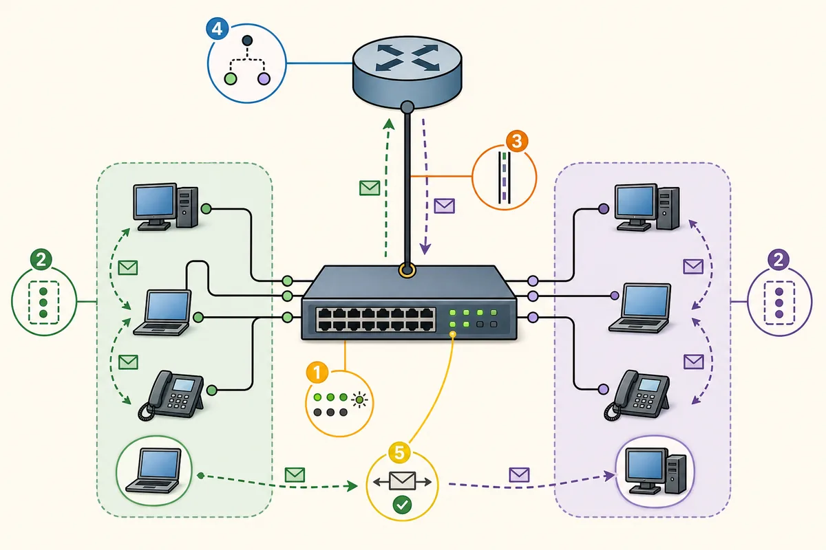
- 1
Enable the parent interface
On R1, enter the physical uplink and run
no shutdown. - 2
Create VLAN 10 subinterface
Use
interface g0/0.10,encapsulation dot1Q 10, and gateway 192.168.10.1/24. - 3
Create VLAN 20 subinterface
Use
interface g0/0.20,encapsulation dot1Q 20, and gateway 192.168.20.1/24. - 4
Verify Layer 3 evidence
Check
show ip interface brief,show ip route, and cross-VLAN pings.
| Interface | 802.1Q tag | Gateway address | Connected network |
|---|---|---|---|
| G0/0.10 | 10 | 192.168.10.1/24 | 192.168.10.0/24 |
| G0/0.20 | 20 | 192.168.20.1/24 | 192.168.20.0/24 |
| PC-A / PC-B | Access VLAN 10 | 192.168.10.1 | Same-VLAN and routed tests |
| PC-C / PC-D | Access VLAN 20 | 192.168.20.1 | Same-VLAN and routed tests |
Verify and troubleshoot the VLAN setup in order
Use a layered check instead of changing several commands at once. First inspect cable and port state. Then verify host addresses and masks, access VLAN membership, trunk status, router subinterfaces, default gateways, and connected routes. Finally repeat a same-VLAN ping and a cross-VLAN ping. This order prevents a missing cable from being mistaken for an inter-VLAN routing failure.
The most common mistake is a mismatch between the four VLAN identifiers: the access VLAN on SW1, the VLAN allowed on the trunk, the encapsulation dot1Q value on R1, and the host's gateway subnet. All four must agree. A second common mistake is configuring a correct subinterface while leaving the parent interface shut down. Use the command output as evidence before editing the configuration.
If the VLANs are correct but a policy still blocks traffic, inspect ACLs only after basic forwarding works. The ACL examples guide covers filtering intent; this page stops at the VLAN segmentation and routing boundary so the two topics do not cannibalize each other.
- Run
show vlan briefon SW1 to prove access-port membership. - Run
show interfaces trunkto prove the uplink carries both VLANs. - Run
show ip interface briefon R1 to prove subinterfaces are up/up. - Run
show ip routeto prove both VLAN networks are connected routes. - Test same-VLAN, gateway, and cross-VLAN pings separately and record each result.
| Symptom | Check first | Likely cause | Useful evidence |
|---|---|---|---|
| PCs in the same VLAN cannot ping | Host address, mask, cable, access VLAN | Wrong subnet or port membership | PC IP panel and show vlan brief |
| One VLAN works across the router, the other fails | Trunk allowed list and matching tag | VLAN missing on trunk or wrong dot1Q ID | show interfaces trunk and subinterface config |
| Both VLANs fail to reach the gateway | Parent interface and subinterface state | Uplink down or parent interface shut | show ip interface brief |
| Gateway ping works but remote host fails | Host address and return path | Wrong mask, duplicate IP, or host firewall setting | PC configuration and two-way ping |
| show vlan brief looks right but no trunk | Uplink interface mode and link | Uplink is access mode or wrong port | show interfaces switchport and show interfaces trunk |
Packet Tracer VLAN setup FAQ
How do I create a VLAN in Packet Tracer?
Open the switch CLI, enter global configuration, create the VLAN with vlan 10 or another ID, give it a name, then assign the intended host ports with switchport mode access and switchport access vlan 10. Verify with show vlan brief.
What is the difference between an access port and a trunk?
An access port carries one end device in one VLAN. A trunk carries multiple VLANs between network devices, using VLAN tags so the receiving device can preserve the separation.
Why can hosts in the same VLAN ping but different VLANs cannot?
Same-VLAN traffic can switch at Layer 2. Different VLANs need a Layer 3 gateway, a working trunk, matching router subinterfaces, and the correct default gateway on every host.
Which commands verify VLANs in Packet Tracer?
Use show vlan brief for access-port membership, show interfaces trunk for the uplink, show ip interface brief for interface state, and show ip route for connected VLAN networks.
Do I need router-on-a-stick for inter-VLAN routing?
It is one common Packet Tracer lab method, using one physical router interface with subinterfaces. A multilayer switch can route VLANs differently, but use the topology and commands supported by your activity.
How do I troubleshoot inter-VLAN routing in Packet Tracer?
Check access VLAN membership, trunk status, matching VLAN IDs, router subinterfaces, parent-interface state, host masks, and default gateways in that order. Then repeat gateway and cross-VLAN pings.
Official references
- Cisco Networking Academy Resource Hub
Official destination for current Packet Tracer resources and course lab materials; sign-in may be required.
- Cisco Packet Tracer product page
Official product overview and access path. Cisco controls release and package details.
- Cisco Packet Tracer 9.0 announcement
Historical Cisco Community release announcement; the current package should still be confirmed in the Resource Hub.